![]()
February 2022 - Extra
Why Diesel?
By Paul Harvey
Coolspring Power Museum worked diligently all last year
upon Diesel Centrale CPM, an installation to display three vintage
Diesel engines. We certainly believe that these engines are very
significant for the enthusiast and visitor alike. But, why Diesel
engines? One might ask how they are significant compared to all
the fine gas engines that the museum displays? Good question, so
let’s go on a bit.
What is a Diesel engine, and how does it differ from a
gas engine? Simple! The Diesel employs a much higher
compression pressure, heating the air in the cylinder hot enough to
ignite the fuel when injected. The gas engine uses lower
compression pressure and employs a spark plug to ignite the fuel.
OK. Both engines burn fuel and produce power. But why is one
better than the other? The Diesel is more efficient due to its
higher compression and heavier fuel. Whoops! I’m getting
ahead of the story.
So now, let us time travel back to the 1800s and look at
two great German engineers who were pioneers in early engine
development. They lived a generation apart from each other, and
each made a contribution that is making our lives more pleasant today.
First, we will meet Nicolaus Otto, born 1832 and died
1891. In 1876, he developed the four-stroke cycle gas engine which
is still the mainstay of our lives today. Yep! One is in your
car! What an invention for all of us!

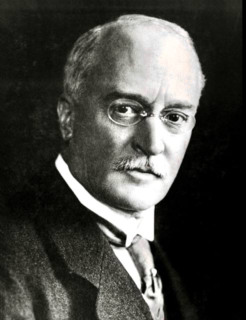
Now we meet Dr. Rudolph Diesel, born 1858 and died 1913.
Working with Maschinenfabrik Augsburg, he produced the first compression
ignition engine in 1897. A new era of engines began! His
engines are used today worldwide, from cars to trucks, to heavy
equipment, and to the largest ships.
CPM’s Augsburg engine, serial number 185, was
built in 1903 when he was at the factory. Wow! That’s
significant. Perhaps he looked at it and approved. It is
still here today.
Now, let’s just get a bit technical and explore the
differences of the machines created by the two great engineers. I
think it can be simple and amazing. We’ll give it a try!
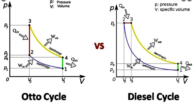
These images are indicator card diagrams of what happens
in the cylinders of both the Otto engine and the Diesel engine during
operation. Don’t look much alike, do they? Well, there is a
simple explanation and let’s take a look. First, note that the
cylinder pressure is shown on the vertical line, and the cylinder volume
is on the horizontal. Any ideas yet?
OK. I will explain. But first, I will
confuse you more to say that the Otto cycle shows constant volume
expansion and the Diesel cycle shows constant pressure expansion.
So here is the little secret!
Let’s start with the Otto cycle. First look at the
blue line from 1 to 2. Got it? That represents the engine’s
compression stroke. At 2, the engine’s fuel is ignited by the
spark plug and the pressure goes up to 3, as shown by the red line.
Increase in pressure but not in volume, so constant volume expansion.
This is the engine’s power. Now go from 3 to 4, the yellow line.
Higher pressure as the engine produces its power. The green line
from 4 to 1 represents the exhaust, and we are back to the beginning!
Hmm! Simple!
Now, let’s look at the Diesel cycle. Somewhat
similar, but a very big difference. Again, the blue line from 1 to
2 shows the engine’s compression. Then, at 2, the fuel begins to
be injected. Yes, it is injected slowly as opposed to the big bang
of the Otto cycle. The red line from 2 to 3 shows the combustion of the
fuel, increasing the volume inside the cylinder, but not the pressure.
Just inject more fuel during combustion and get more volume, pushing the
piston down for more power. Smooth and efficient! Hence, we have
constant pressure expansion. The yellow line from 3 to 4 is the
power of the engine. The green line from 4 to 1 is the exhaust
stroke, taking us back to the beginning again. Think about it a
bit, and it becomes simple! Now you know the difference.
Great.
Note that the area inside the four colored lines
describes the amount of useful power that the engine produces. Simple,
huh?
Both these cycles are still very practical for us today.
The Otto cycle can use lighter engines very practical in automobiles,
lawn mowers, garden tractors, and the like. Then the Diesel cycle
is used in trucks, heavy equipment, ocean going ships and all similar
uses. We owe the two men a lot to make our lives easier and more
pleasant today.
INJECTION TYPES FOR DIESELS
Now, I would like to take a brief look at the types of
fuel injection for the Diesel engines. We will chat a bit about the
three main categories: air-blast injection, solid injection, and common
rail injection. Don’t worry, these concepts can also be simple!
AIR-BLAST INJECTION
Air-Blast Injection is Dr. Diesel’s original design and
is used on the engines that will be displayed in CPM’s new building,
Diesel Centrale CPM. The museum’s Augsburg engine uses this
principle.
So how does it work? The Diesel engine has a
compression pressure of about 500 psi, so compressed air at 800 psi is
needed to “blast” the fuel into the cylinder for combustion. This
method provides for fine atomization of the liquid fuel. Fine
atomization provides for more oxygen exposure, which yields better and
more complete combustion. Let’s take a peek!
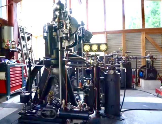
This illustration shows a basic early air-bast injection
engine. Note the air compressor attached to the left side of the
engine. It’s supplying air to the storage bottle as well as to the
injector on the top center of the engine. At the precise moment,
the cam shaft, top right, by a rocker arm, opens the injector and
combustion begins. Yep, the engine produces power. Got it?
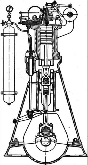
The system worked well, but was cumbersome and fraught
with all sorts of problems. But it was the start! It
will soon get better.
This is Dr. Friedrich Busch’s 12 hp Augsburg-Nurnberg
type DM air-blast engine. It is a few years later than our
Augsburg engine. Note the two-stage air compressor at the right
base of the engine, and the pressure gauges and air tanks.
I am honored to have been allowed to start it with his
supervision.
SOLID INJECTON
As the years passed, metallurgy and machining progressed
to the point that an injection pump could be made to directly deliver
high pressure fuel to the injectors. Pressures exceeding 20,000
psi were needed. This development did not happen until the late
1920s, but it eliminated the air tanks and air compressor. Wow.
One small pump with lines to the injectors. Simple! Since the
fuel is a non-compressible liquid, the process was termed “solid
injection.”
We will take a peek at the two basic types.
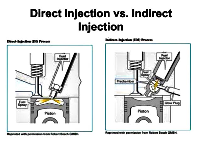
Direct injection, shown on the left, placed the injector
in the cylinder, direct from the fuel injection pump. Combustion
occurred in a well in the piston. This system was used in the
earlier Dodge pickups with Cummins diesels, and employed a mechanical
Bosch injection pump. It was simple and very effective.
Indirect injection used a pre-combustion chamber, often
warmed by a glow plug for starting. The pre-ignited fuel was then
discharged into the combustion chamber, where the ensuing combustion
took place. Some of the other truck engines used this principle.
Both systems are in common use today and are very
successful. Still with me? It’s simple!
COMMON RAIL INJECTION
This is the third and last category that I will discuss.
It’s been around a long time and now popular again. So, let’s take
a peek and make it easy.
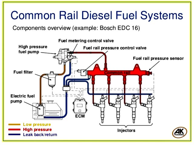
Just as the name implies, there is a “common rail” or
fuel manifold that is pressurized to 30,000 psi or above, that supplies
the fuel to the individual injectors. This arrangement is shown in
the red portions above. The fuel tank is seen at the lower left in
the illustration above. A fuel pump delivers the fuel through a
filter to the high-pressure pump. This flow path is shown in
yellow. Still with me? Trying to keep it simple!
The high-pressure pump, remember- over 30,000 psi now,
delivers the fuel to the fuel manifold or “common rail.” The
injectors act at the precise time, either by mechanical or electronic
means, to put the fuel into the cylinder to be burned. Wow.
The engine is now getting power. Any overflow or leakage is
delivered back to the fuel tank by the blue lines. Simple, but
very effective! Got it?
This common rail injection system atomizes the fuel into
very fine droplets which have more oxygen exposure, giving better
economy. Interesting that this result was what Dr. Diesel was doing in
1897 with his air-blast injection! Technology advances, but the desired
end is the same!
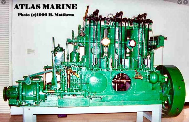
It is interesting to note that Atlas Imperial Diesel of
Oakland, California, developed a common rail engine in the 1930s.
These engines were both successful and beautiful.
There are many other variations of injection for Diesel
engines, but air-blast, solid, and common rail are the basic types.
The others are beyond the scope of this article.
It is my hope that the reader has found this article
about the operation of the Diesel engine both informative and easy to
understand. I have enjoyed writing it and I hope you have enjoyed
reading it.