![]()
April 2016
An Engine Named Gus
Part 1: Gus and His Designer
By Paul Harvey
I first met Gus back in 1971 when my
wife and I were vacationing in
Sadly, I did not understand Gus. It was unclear to me how he could have operated! The other two engines were put on display in the museum, but Gus was stored in the old garage to wait for a day to live again. Forty five years later and perhaps a bit smarter, and with the help on the internet, I learned what a complex and wonderful engine Gus is. Despite the metallic blue paint and white flywheels, he is now in my shop being prepared to live again. I will share these details with you.
Gus's designer was a young Swedish
immigrant named Gustaf Joranson. Hence the Gus name. His image is
shown as Photo 1. Joranson was born on
In 1893 Joranson married Hansine
Amundsen Hansen, a Norwegian immigrant. They had four children, and
lived at
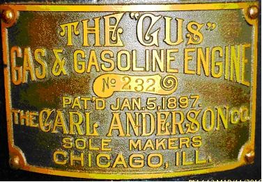
Joranson had two patents on his engine
design, the latter assigned to the Carl Anderson Company. His first
patent on
Photo 4 is a 1902 advertisement for the Gus: identical to and before the 1903 patent. Note that there are "None Better!" Continuing with Photo 5, we see the majestically handsome Gus horizontal engine. Note the excellent proportions, great workmanship, and fine lines to make a very pleasant engine. This engine is identical to the 1903 patent.
A Gus saw rig is shown at an exhibition in 1905. This display appears in Photo 6. The only mention of electric ignition that I discovered is found in this Modern Machinery article. "The engine is equipped with both hot tube and electric igniters, which enables it to run in all sorts of weather." All other illustrations show just the hot tube mounted in the intake valve cap.
The Gus living at Coolspring is a vertical model, which is the 1903 patent rotated ninety degrees. It is similar in all its mechanisms, which are very unique. Basically, the engine is a four-cycle, throttle governed design with a ported cylinder. His cylinder bore is 4 1/8 inches and stroke is 6 inches. There is one eccentric on the crankshaft and no timing gears. A pressure operated device on the valve chest senses compression pressure and engages a lever that activates the exhaust valve. Hence the four-cycle design. It is governed by a "porkchop"-like weight in the flywheel that limits the stroke of the intake valve, hence the throttling governor. The electric igniter is piston-tripped, eliminating any outside mechanism. As I studied Gus, I pondered about how this could possibly work successfully. Then I looked at all the carbon deposits inside Gus, and all the wear on his parts, and realized that it had worked well for many years. Now we will see how this all fits together.
Photo 7 is Gus's front
side. The base and cylinder are all one casting which required
extensive machining for all the parts to be in alignment. This overall
profile is similar to other vertical engines built in
Photo 9 shows the rear of the engine. The water inlet is at the base of the cylinder, and the large exhaust port dominates the back side. The valve chest appears on the top left, and the exhaust from the valve is ported through the cylinder to the main exhaust port, further complicating the casting design. The lever that engages the exhaust valve can be plainly seen. Photo 10 details the head and the piston-tripped igniter. On the inside, the igniter is not complete. The intake valve cover now has a spark plug, which was a later modification. This would have been the location of the hot tube.
Photo 11 is a detail of the valve chest, the pressure operated exhaust valve latch, and the gasoline overflow bowl. The governor rod reaches this area and controls the tension on the intake valve spring, hence regulating engine speed. Not present in the photo, there would have been a 3/4 inch pipe that entered the intake valve opening and turned downward. A tiny pipe would have entered its side to admit gasoline into the upward air flow. This primitive "carburetor" was typical on many early engines and worked well. Photo 12 pictures the one large eccentric on the crankshaft and the large exhaust valve roller above it. The governor is on the flywheel and a large torsion spring can be latched into several pegs to adjust the engine speed. Finally, Photo 13 shows the fuel pump which supplies a continuous amount of gasoline to the overflow bowl. Gus is, indeed, a unique and complex engine. He will be proudly on display at our June show.
I wish to acknowledge the following sources of information that I used to make this article possible:
Ancestry.com
Next month, I will take you to
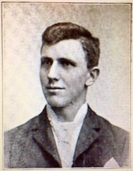
Photo 1: Gustaf Joranson
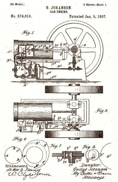
Photo 2: First Gus patent
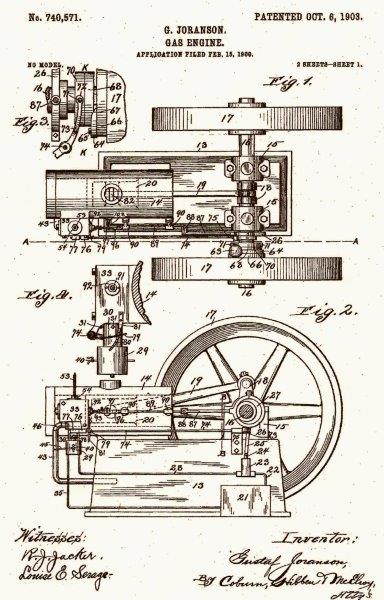
Photo 3: Second Gus patent
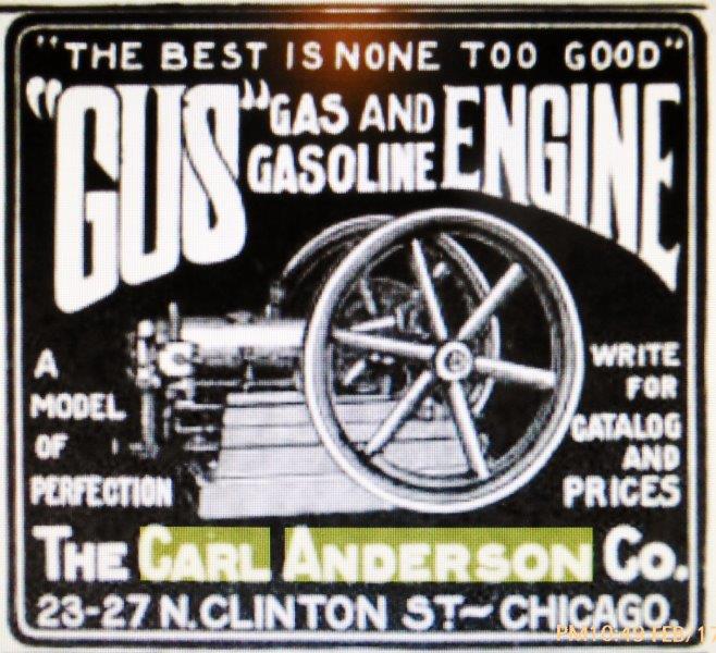
Photo 4: Gus 1902 ad
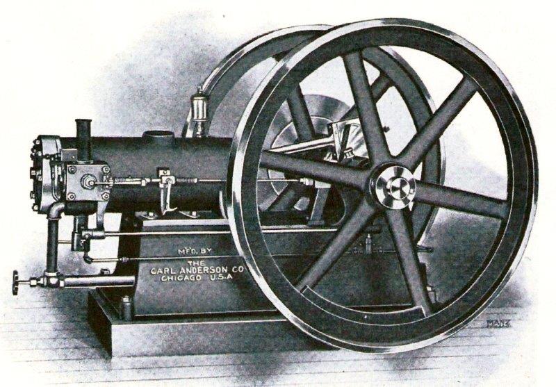
Photo 5: Gus horizontal engine
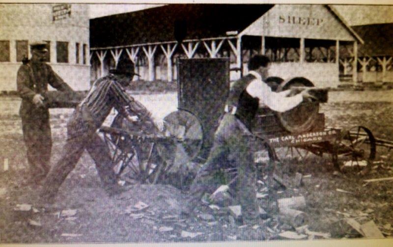
Photo 6: Gus saw rig 1905
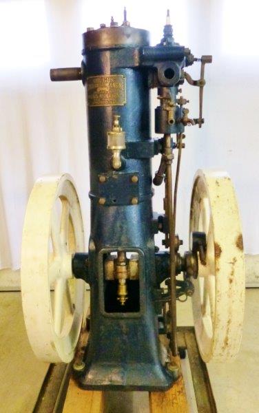
Photo 7: Gus front
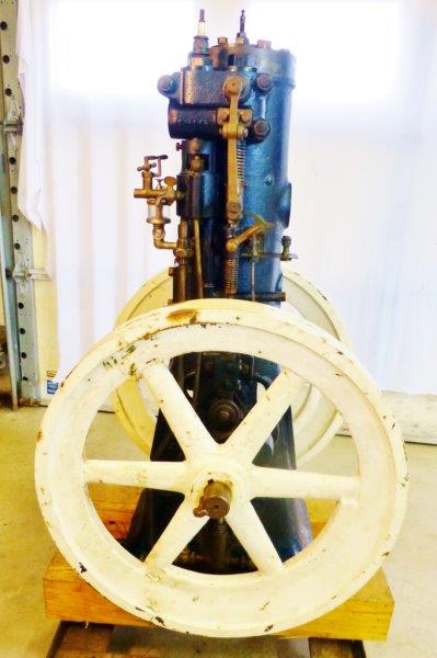
Photo 8: Gus side
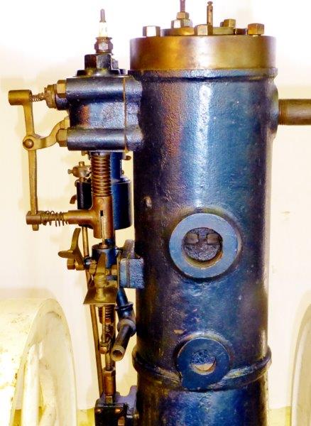
Photo 9: Gus rear
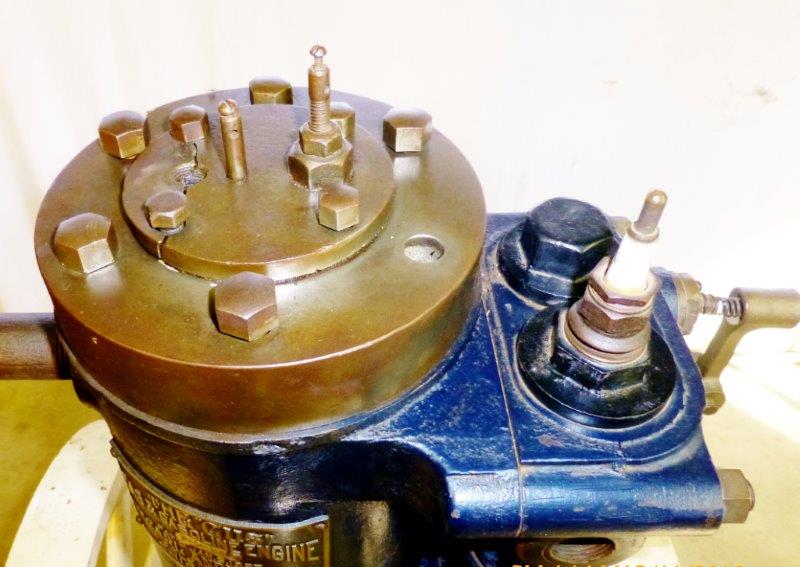
Photo 10: Gus piston trip igniter
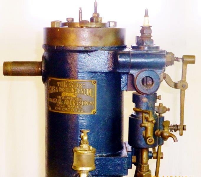
Photo 11: Gus mixer
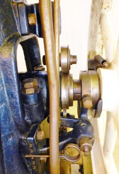
Photo 12: Gus governor
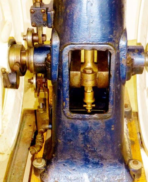
Photo 13: Gus fuel pump