![]()
March 2014
Snow Part 2: The Engine
By Paul Harvey
Last month's Flywheel was the first of a two part article
about the Snow gas engine and in it we explored the history of the
inventions that led to the development of this engine. We learned of
the intertwining of the persons and their ideas that formed these great
machines of the past. In this article, we will follow our Snow from
when it was first seen, to the present, as an operational display at
Over 45 years ago, I first stumbled upon Roystone
Station, which was located on route
Roystone was the main station of the Pennsylvania
Natural Gas Company based in
In the mid-1970s, and with no definite plans besides the desire to save one of the big Snows, I started a lasting relationship with the plant engineers and local administration and was happy to find them receptive of the idea. Finally, in late 1992, I was invited to come to Roystone to witness the last working day of our Snow. Shortly thereafter, I met to sign the documents on behalf of the museum to make the Snow ours. We now had the winter to remove it, that would be to disassemble and transport a 140 ton machine and place it in safe storage until it could be assembled again. This would be a twenty year project.
The volunteers of the museum took the task seriously, with six or eight of us trekking to Roystone many weekends. Photo 3 shows our engine to the right with some parts already laid out on the floor. Note that the compressor cylinder has been removed and is hanging on the manual chain-fall crane to the left rear. It would then be transferred to the front crane and travelled to load onto our truck. This was a tedious and labor intensive project frequently requiring six people to pull the hand chain to lift the heavy parts as the hoists were entirely manual.
The next project was to remove the flywheel from the crankshaft. The wheel weighed 18 tons and split into two halves. Being held together at the hub by four huge bolts, four inches in diameter, and at the rim by four cast iron keys or "dogbones", it proved to be a challenge. Photo 4 shows the task of heating these keys red hot for expansion and then pulling them out with a manual chain puller. Each weighed about 150 pounds and had to be supported with the overhead crane. We then found that they were a bit different in length so had to be carefully marked for reassembly.
Photo 5 depicts a flywheel half, weighing nine tons, loaded onto my dependable old "tilt bed," a 1976 International 2070A Fleetstar with a 290 hp Cummins engine and nine speed Roadranger transmission. Note the size of the doorway that the entire engine had to come through! I always drove my truck and had some unusual experiences on the ice and snow that winter. Once home, the truck had to be unloaded, and the parts stored appropriately, so it would be ready for the next weekend. Everything came home on this truck except the 34 ton main frame.
The main frame for the engine was a huge project and Photo 6 shows it jacked out of the foundation awaiting rollers to take it out of the building. Note that the crankcase bottom extends one foot below the base. This, in addition to ten feet of unsupported floor between the engine foundation and building footer, required a huge amount of timber blocking to get it outside of the low, narrow doorway.
Smith Hauling of neighboring
National Fuel Gas Corporation kindly allowed us to use their vacant Knox Station, about five miles from Coolspring, for storage of the Snow parts. They realized that it would be many years before they came together again. However, some of the large parts had to be stored outside at the museum. Photo 9 shows the compressor cylinder, earlier seen in Photo Three, ready to unload into the station. Again, a small doorway and unsupported floor was encountered which required using the ten ton manual chain hoist to position the parts. Interestingly, this structure originally housed two massive National Transit gas engines and their foundations provided stable support for our storage purpose.
After much planning and funding work, we now jump ahead about ten years to see the area for the erection of the Snow being cleared in June 2005. Shown in Photo 10, the brush is removed and a stable shale fill is installed. The twenty year project has begun here at Coolspring!
After all the leveling and fill, a big hole was then dug to accommodate the huge concrete foundation. When the engine was removed from Roystone, our volunteers spent several days measuring the old foundation to produce a computer generated foundation plan for re-erection. We trusted that it would be accurate and all the mounting bolts would line up. Finally completed in October 2005, the foundation required 287 yards of concrete being done in two pours. The first was a massive flat base pad three feet thick, and the second was the foundation itself. A concrete pumping truck worked an entire day to fill the frames. After several weeks, the framing is removed in Photo 11. It would now require many months for the concrete to cure so that the parts could be placed upon it.
In May of 2006, seen in Photo 12, the
big test came. With the aid of Smith Hauling again, the main frame was
set. They loaded it from where it rested for many years onto one of
their trailers and carried it to the foundation where they placed it
with their crane. They had already placed the bottom flywheel half onto
blocking in the pit. The main frame fit the many bolts...well, almost!
One shifted during the concrete pour and had to be adjusted, and then
it was in place. Now, another big job of leveling a 34 ton casting and
placing the grouting began. Also, grating needed to be cut and fit to
cover the pits needed for future piping and accessories to make a safe
work place. All further assembly was then done with the museum's
Now was time to retrieve all the parts that had been stored in Knox Station so many years before. After each piece was brought to the re-erection site, it had to be cleaned and serviced before placing onto the foundation. The last big part to retrieve, as it was the first stored, was the compressor cylinder that has been seen in Photo Three and Photo Nine. Photo 13 shows a satisfied crew with the 10 ton compressor again loaded onto the old "tilt bed" truck for the short trip back to Coolspring. This was September 2007, and it had yet to be cleaned and prepared for the coming winter.
The next year, 2008, saw the engine taking form and
coming together. So much work had already happened without seeing a
final product that this would be a pleasant job. It was now going to
look like that massive 600 hp Snow again! In June 2008,
Photo 14 shows the cylinder base plate and rear cross head
casting in place and the rear power cylinder being lowered into place by
the
Photo 15, in July 2008, shows the
The next year, 2009, witnessed continuing progress of
assembling the engine's main components, which required overhead room
for the
By spring of 2010, the crew had accomplished all the "big" projects and the engine really looked like itself again, although now much detail had to be addressed. All the pipe work for the natural gas supply, the air intake, the exhaust, the lubrication system, the cooling water supply and discharge, and the starting air needed to be done. This required countless hours of cutting, threading, and placing pipe from 1/8 inch to 10 inch diameter. Ancillary to the engine, a water cooling system with buried sump tanks and tower mounted tank had to be installed. A huge air tank for compressed starting air had to be installed and tested. In all, over 1,000 feet of pipe was used. Next came a new electric service entrance to supply all the lights and pumps. It was a big year of tedious work.
The final touches began in 2011, as seen in Photo 18 which shows the installation of the ignitors. The coil box was mounted and 800 feet of ignition wire was placed into conduit to make the system operate. The next two years were busy with progress on all the engine support systems. This even included final grading and gravel placement to make the area more presentable.
Finally the big day came during our June 2013 Show. After so much diligent work, the crew decided to try to start the engine. This was the Tuesday evening of show week and a formal run was not planned until the October show. However, with all ready and relative privacy, the crew started the air compressor, filled the starting tank, and turned on the lube oil. Photo 19 shows the event as Chris manned the controls and the crew watched. It slowly rolled on starting air and then fired on the third revolution of the big wheel! The rest of the crew watched all the parts as the Snow finally came to life again! It steadied into a smooth rhythm and ran well for the next fifteen minutes. Then it was time to shut down and check all the parts. Very satisfied with the great start and operation, it ran for all to see several others times during the show. Twenty years since dismantled at Roystone, the Snow "lives" at Coolspring.
The formal dedication ceremony was done on
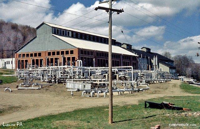
Photo 1: Roystone Station in 1963 (Photo by Robert Pence)
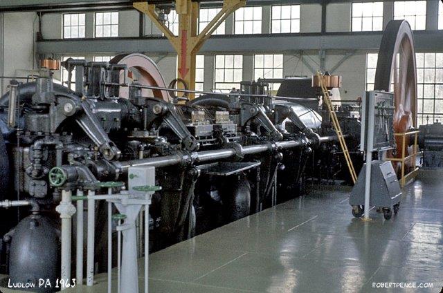
Photo 2: Our engine at Roystone in 1963
(Photo by Robert Pence)
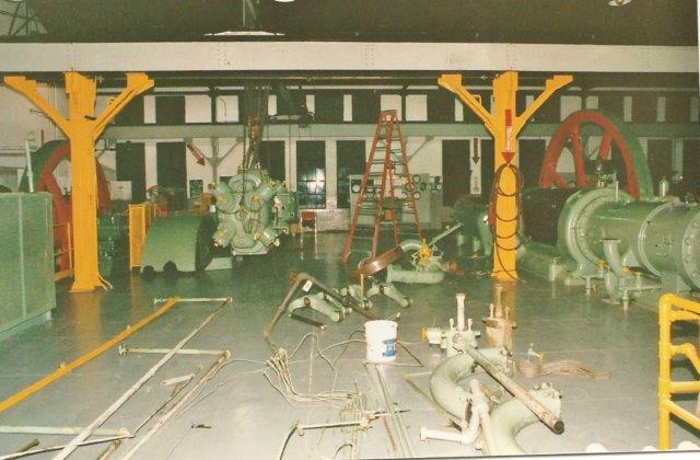
Photo 3: Disassembly begins
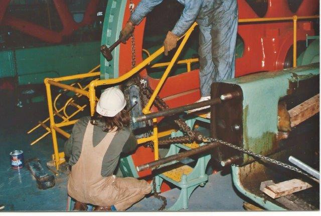
Photo 4: Removing dogbone keys from the flywheel
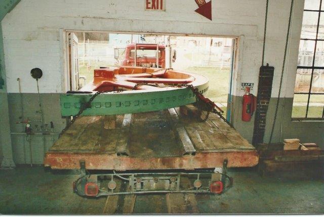
Photo 5: Flywheel half on tilt bed
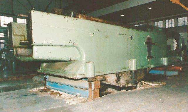
Photo 6: Main frame jacked up for removal
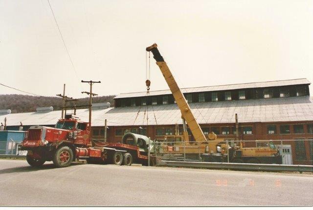
Photo 7: Main frame loaded for transport the the musuem
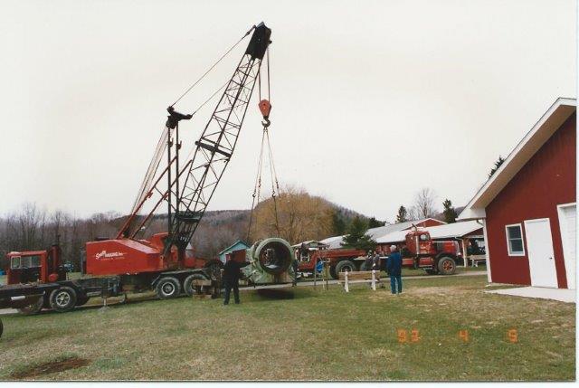
Photo 8: Unloading the main frame at the museum
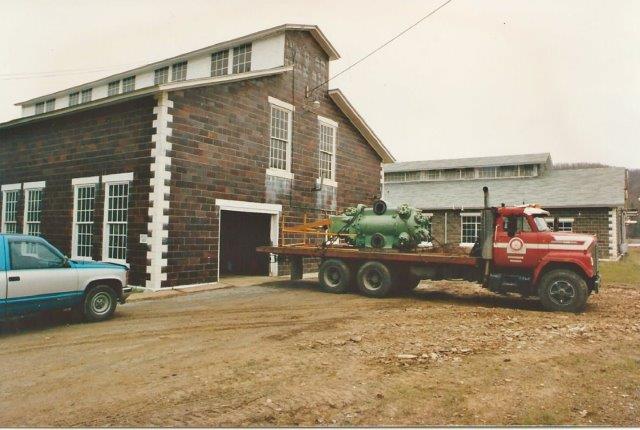
Photo 9: Placing the compressor into storage at Knox Station
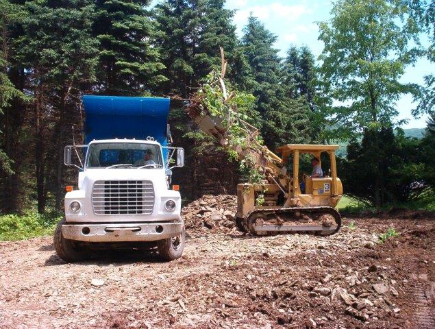
Photo 10: Clearing the site in June 2005
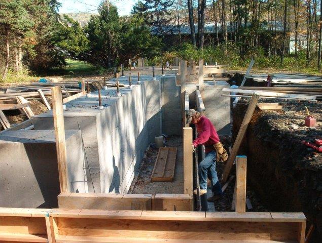
Photo 11: Foundation forms being removed in October 2005
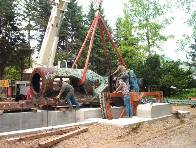
Photo 12: Placing the main frame in May 2006
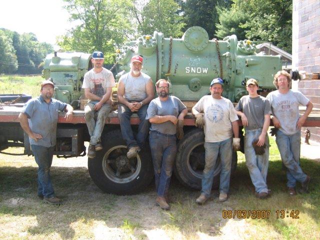
Photo 13: Compressor being removed from storage
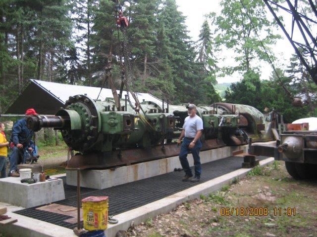
Photo 14: Reassembling the engine in June 2008
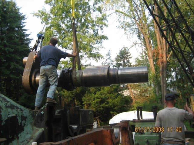
Photo 15: Installing the crankshaft in July 2008
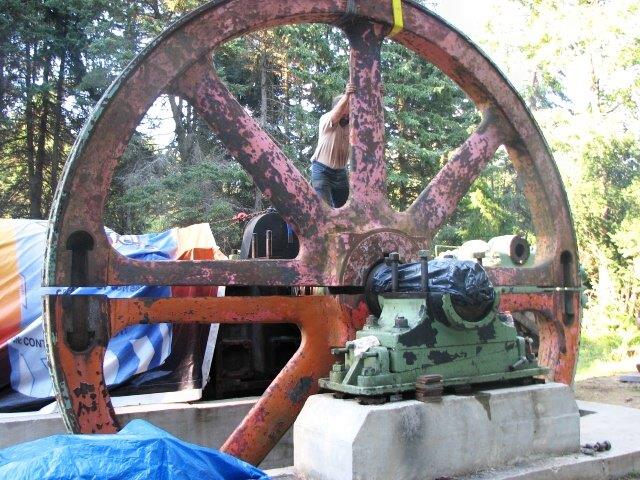
Photo 16: Assembling the flywheel in September 2008
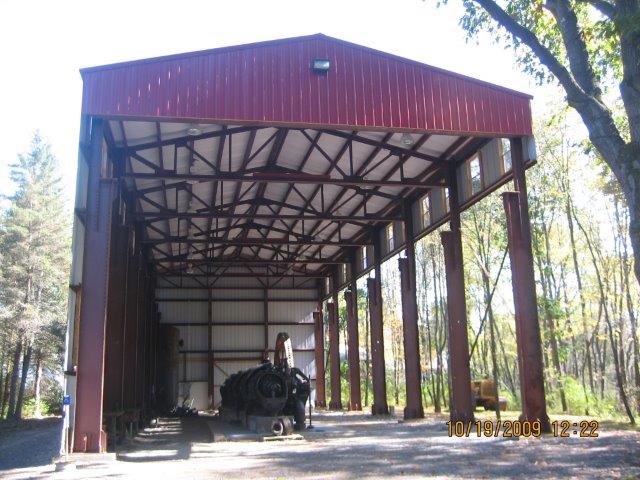
Photo 17: The engine and its building in October 2009
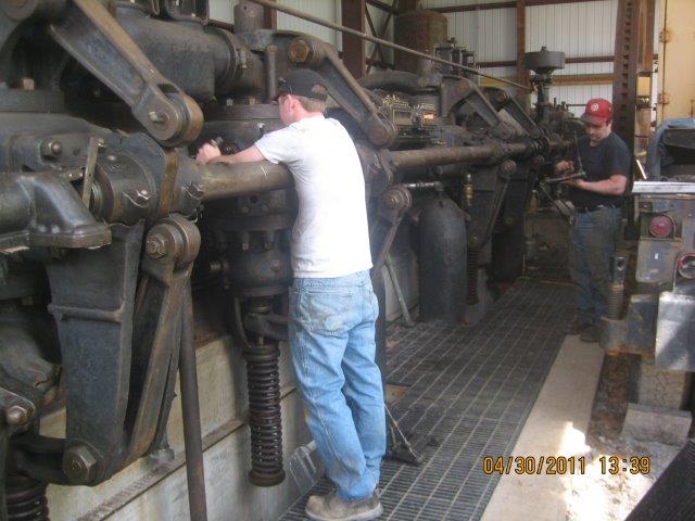
Photo 18: Installing ignitors in April 2011
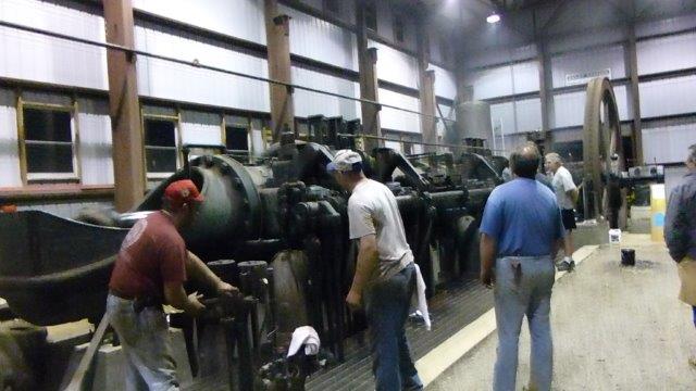
Photo 19: First run in June 2013
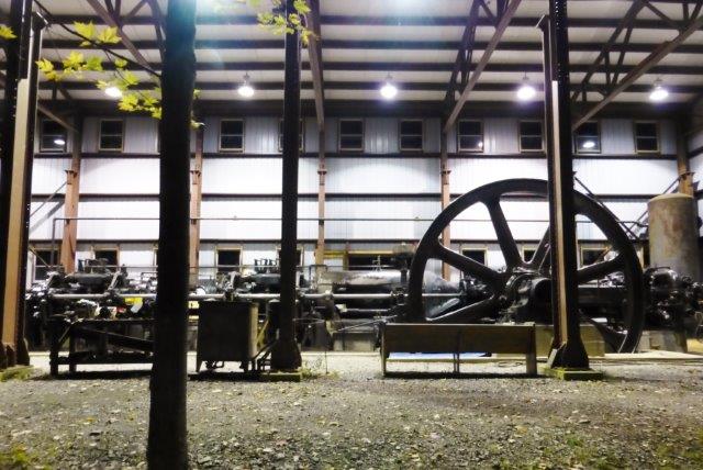
Photo 20: The night before its debut in October 2013