![]()
January 2013
Cast Iron Art
By Paul Harvey
The calendar has just rolled over another year and the
joyous excitement of the holidays is a mere memory. But now we are
looking forward to spring with the days getting longer and the sun
warmer. The museum is excited about the coming season and progress
has happened all winter. The June Show will be only a moment away
as time seems to go so quickly. We plan to be able to run the 600
hp Snow at that time if all continues to go well. Our featured
engines for 2013 will be Oil Engines and this includes all compression
ignition engines or those that do not use electric ignition. More
will be written on this topic in the coming months and I am sure we will
have some very impressive equipment displayed here for the show.
For many years, I have been impressed with the attention
to detail in the old gas engines as well as machine tools, steam engines
and other items too numerous to mention. Parts and surfaces that
could be functional in a rough, as-cast appearance are machined and
polished to be pleasing to the viewer. Bright machined finish,
proportion and even paint schemes are done far beyond that necessary to
make the machine functional. I consider this the art of the old
master craftsman to make not only a working machine but one that is
esthetically pleasing. I have termed this "cast iron art" and will
demonstrate in the following examples. If one just looks closely,
it will be evident.
Photo 1 shows the governor for the 30 hp
New Era engine displayed here. Surely, it would have worked just
as well using unfinished parts. However, note the symmetry of design and
the well finished parts including the linkage and weights. An
interesting combination of metals is used with the blending on cast
iron, brass, and steel. Standing high above the engine, this
governor first catches the eye then draws attention to all the finished
parts of the engine. It is both a beautiful adornment as well as a
necessary functional part.
Continuing with the same engine with Photo 2
is the magnificent name plate. Everyone knows what name (or
information) plates look like today; a mere stamping on a small
piece of metal. But New Era was proud of their product. The
huge plate is cast brass that has been polished then plated with nickel.
But then note the date at the bottom; it is 1894. This
detail, and I call it art, is typical of all the old engine name plates.
The overall proportion of the machines was also
important to make the appearance pleasing. Photo 3
shows a White and Middleton engine displayed here. Note the
graceful vertical lines of the base rising to hold the cylinder by a
tangential shelf and the appropriate size of the flywheels. It all
fits together so nicely to make a very attractive machine.
The flywheel is a very important part of the gas
engine as it provides the rotary motion to keep the crankshaft turning
between power impulses. Many engines can be identified just by
looking at the flywheel design. Photo 4 shows the
unusual (for American makers) spiral spoke wheels of the museum's 1880s
Connelly engine. Note how the spokes sweep toward the hub but
enter it at a tangent instead of directly. I feel that Connelly
wanted to show both motion and interest with this design. It
certainly made their engine more attractive.
Photo 5 shows a typical paint scheme
as many of the old makers used. This early
The crankshaft is the heart of the engine.
The crank can easily be a rough forging with the journals machined and
work very well. As Photo 6 demonstrates, some went
much farther. Notice this well finished crankshaft that includes
counter-weights as used in the Lazier engine. It is done in a disc
shape, most likely for appearance. Many other engines had well
finished cranks with the throws brightly finished. All the extra
detail made a very pleasant machine to view and watch operate.
The earliest maker chose to use a Classic period
design. Photo 7 depicts the base and pedestal
of the museum's 3/4 scale running model of the 1867 Otto-Langen free
piston engine. The base is octagonal and has sculptured cornices
leading to a fluted column. Certainly this external detail did not
make the engine run any better but did apply an artistic appearance.
The engine was a commercial success and the forerunner to the future
Otto designs.
Some engines just have a pleasing appearance and
want you to look more closely. Certainly this little
Photo 9 displays a beautiful
design. This big Callahan has lots of bright machine work
including the head and governor. The flywheels are just right in
size and the lines continue with a cast iron crank shaft cover that
still allows view of the finished crankshaft. The end of the
crankshaft then has a machined bright cover. Its lines flow nicely
making a very impressive engine.
Photo 10 is my overall choice of
appearance. This is an 1893 vertical Olds that was shown at the
Chicago Columbian Exposition. The paint is amazingly intact and it
has a large open crankcase displaying the well finished crankshaft.
The size and dimensions are just right. It has a very intricate
pendulum governor, gasoline hot tube, and lots of brass work. It
is truly a work of art.
Some makers had a good sense of symmetry which is
shown in Photo 11. This is a Miller combination
engine and air compressor. Note how the governor is placed between
the power cylinder and the flywheels. It is directly at the center
of the compressor cylinder and spaced between the two intake valves.
Many other makers also considered symmetry in the placement of the
engine parts.
The lubrication of the engine is a critical part
and there were many manufacturers of these parts. Photo 12
shows the oilers on the 175 hp Otto engine. These are
Lonergans and feature curved glass bowls with the name imprinted as well
as highly machined and finished brass parts. Simpler devices would
have been just as effective but not nearly as artistic and Otto chose
only the best. I think that "oilers" showed a varied art work as well as
functionality.
Detail to the placement of the parts of a gas
engine was important but some makers did it in an attractive manner.
Photo 13 shows the arrangement of the valve, the belt
drive lubricator, and the governor of the 1/2 hp Crossley. These
parts are arranged in both a functional yet pleasing design. This
little engine is English and dates into the late 1880s. It
appears "just right" as it runs at the museum.
Marine engines, due to the operating conditions,
frequently had a lot of brass work due to rust and corrosion problems
with iron components. This engine does it very nicely using lots
of brass for the functionality but also in a decorative manner.
See Photo 14 for a Kahlenberg marine engine that made any
boat's engine room a showpiece. This is truly applying art into
function.
Steam engine designers also appreciated applying
art to their machines. Photo 15 shows the
inlet throttle valve and its lubricator on an 1880s Farrar and Treffts
oil field steam engine. Note the rounded flanges and the globe
design giving symmetry and beauty to a simple valve. The early
steam engines had much detail to proportion and detail and could be the
subject of a future article.
Machine tools also displayed fine finish work and
artistic contours. Photo 16 shows an early
planer displayed at the museum. Notice all the bright work that
really was not necessary as well as the contour of the top casting.
This make the machine pleasant to view as well as use.
It is my hope that the reader will appreciate this
little tour of Cast Iron Art as found at the
The opening of the museum is just around the
corner. Our first open weekend will be April 20 & 21, 2013, and
the big June Show and Expo is June 13, 14, & 15, 2013. Remember
History Day and the Truck Show on July 20 & 21, 2013. For more
information, please call 814-849-6883. Have a great New Year!!!
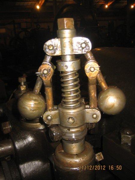
Photo 1: Governor for the 30 hp New Era engine
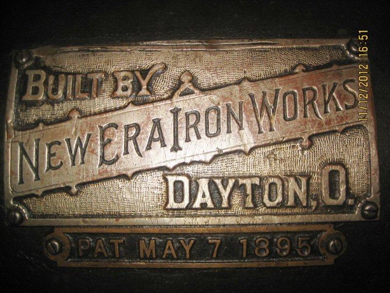
Photo 2: New Era name plate
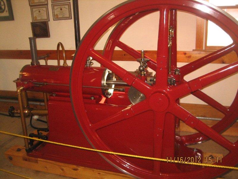
Photo 3: White and Middleton engine
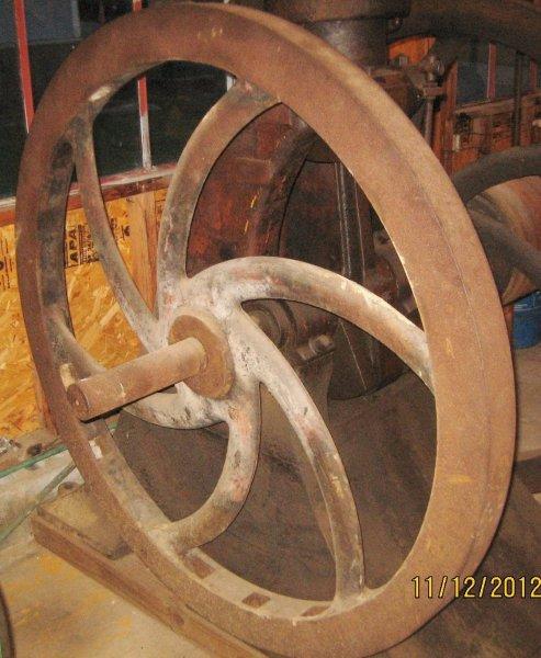
Photo 4: Spiral spoke flywheels of the 1880s Connelly engine
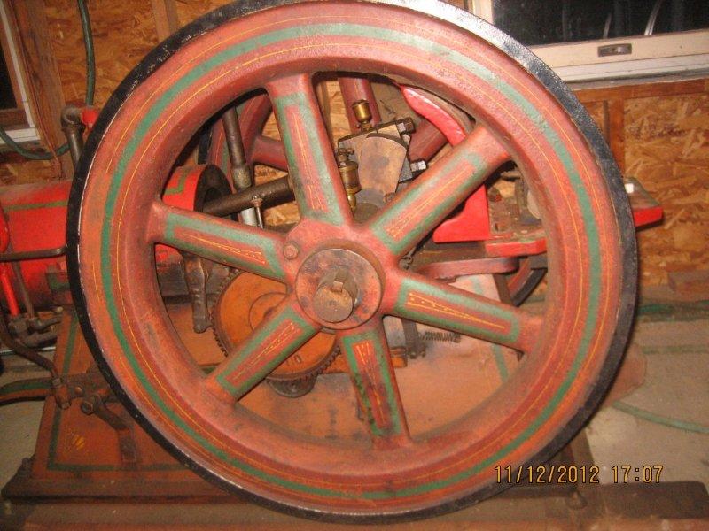
Photo 5: A typical paint scheme on an Alamo engine
Photo 6: A well-finished crankshaft
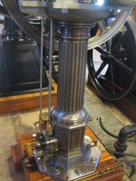
Photo 7: Base and pedestal of the model 1867 Otto-Langen engine
Photo 8: Angola engine
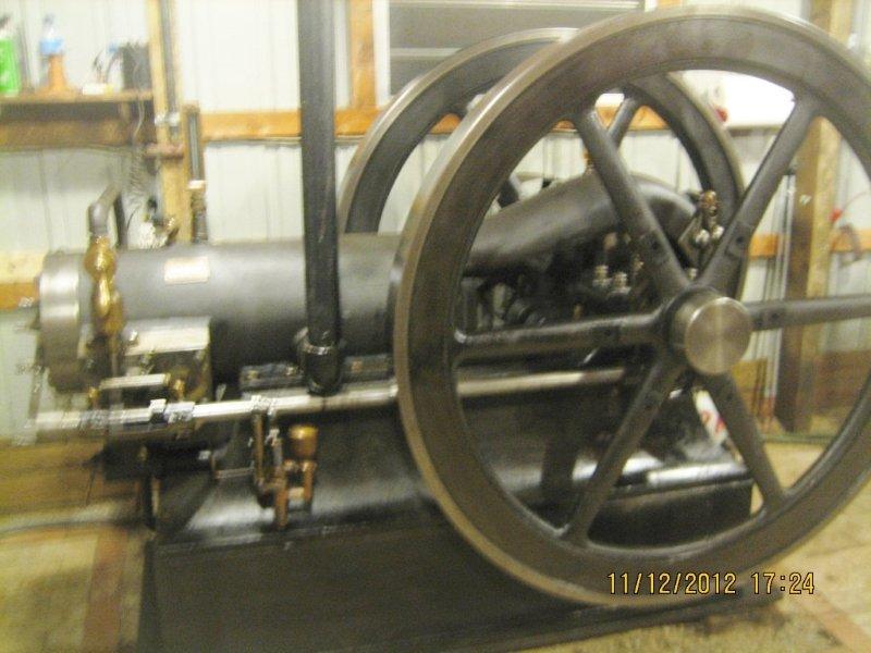
Photo 9: Callahan engine
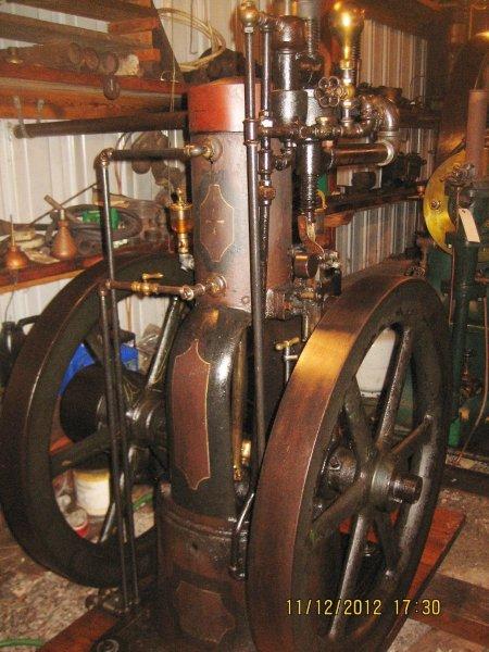
Photo 10: 1893 vertical Olds engine
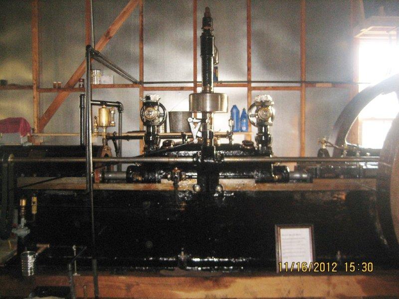
Photo 11: Miller combination engine and air compressor
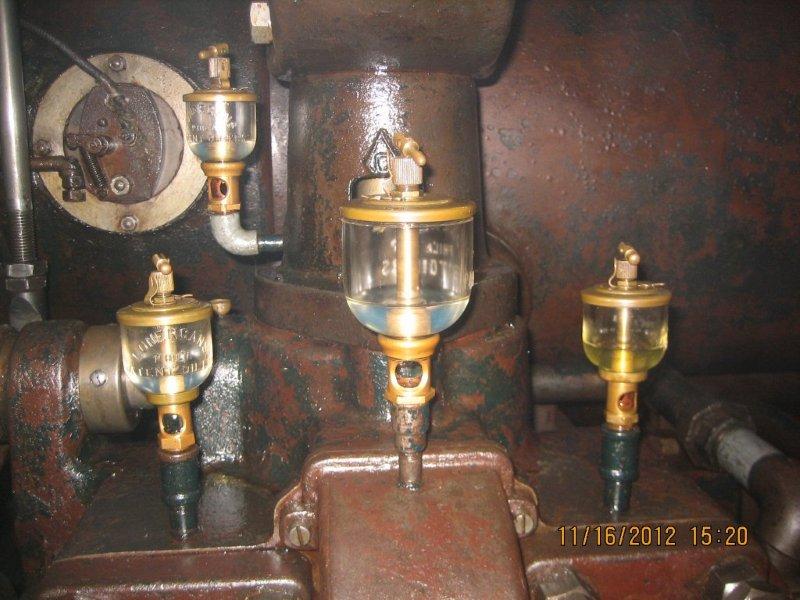
Photo 12: Oilers on the 175 hp Otto engine
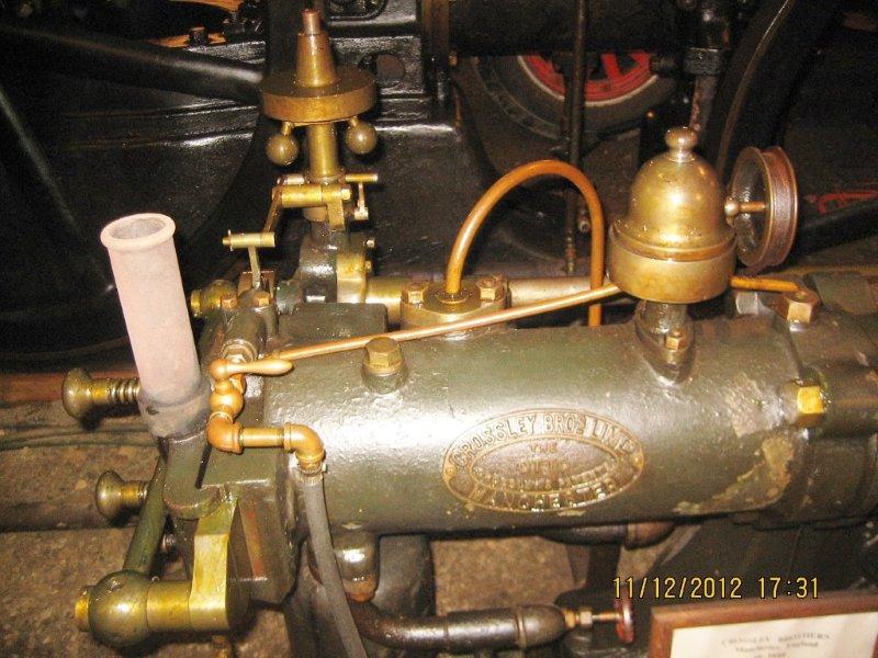
Photo 13: The valve, belt drive lubricator, and governor of the 1/2 hp Crossley
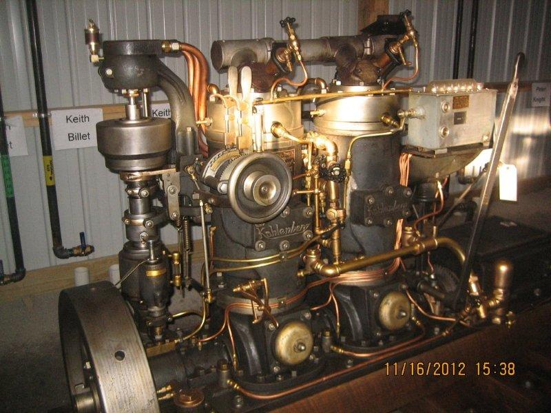
Photo 14: Kahlenberg marine engine
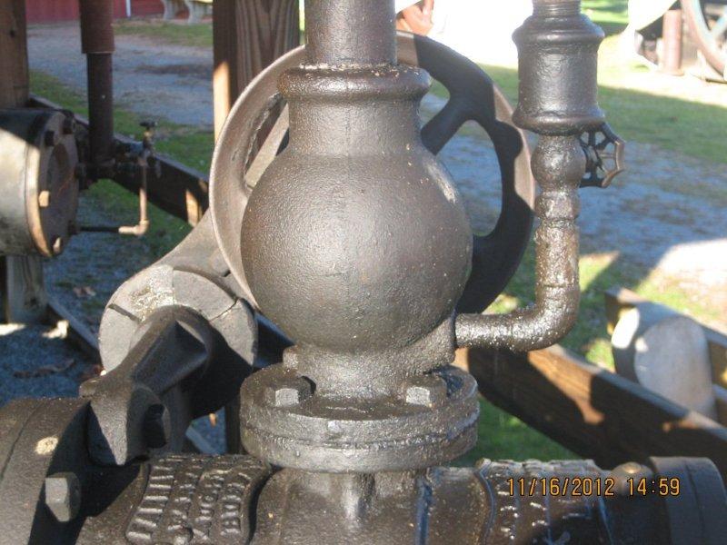
Photo 15: Components on a Farrar and Treffts oil field steam engine
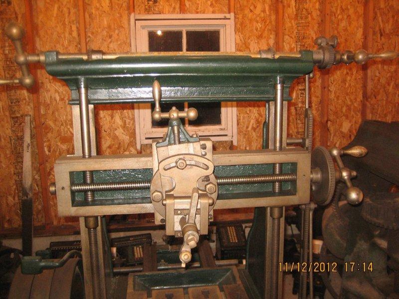
Photo 16: An early planer